Multiple Corrosion Protection Anchors
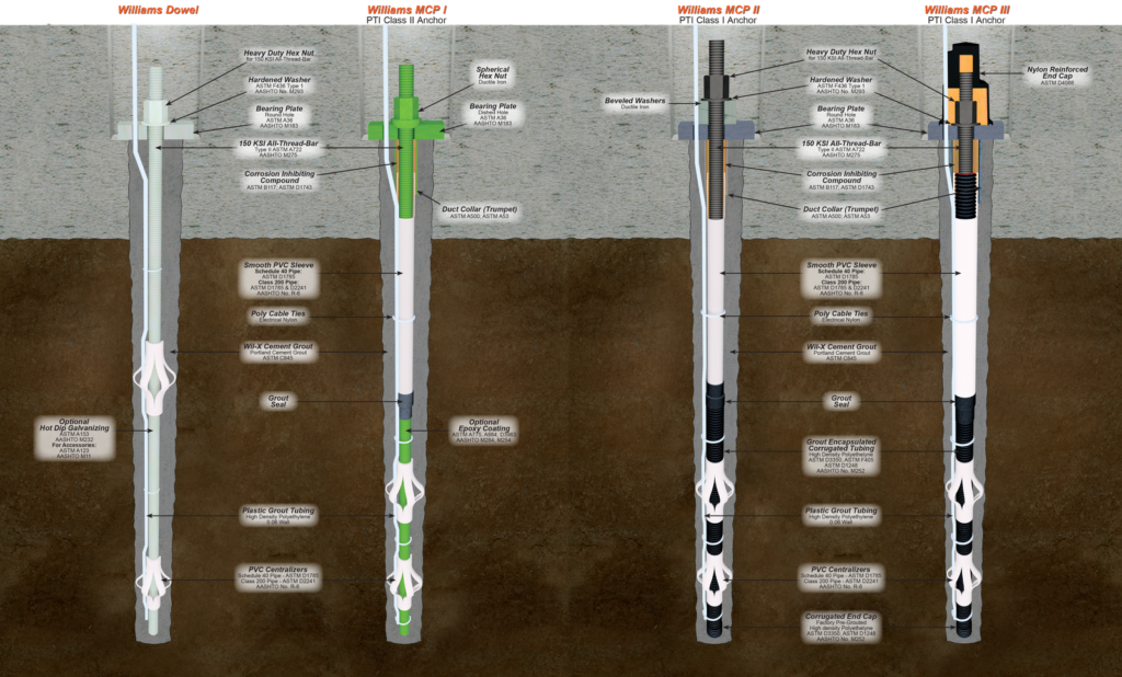
Williams standard grout bonded rock & soil anchors consist of a plain or epoxy coated bar, grouted in an oversized drill hole. Centralizers should be used to assure good grout cover (approximately 25 mm) around the bar. Where anchors will penetrate aggressive soils that are low in pH value (<5.5) and high in sulfate, additional corrosion protection may be desirable. The degree of protection should be matched against the aggressivity of the environment and the expected life of the anchorage system.
Williams Multiple Corrosion Protection (MCP) systems offer increasing barriers against corrosion attack for confidence in permanent anchorage in all ground environments. Williams protective outer end caps may also be used to seal the nut and washer from the environment when the outer end of the anchorage will not be encased in concrete.
Typically, Williams MCP anchors are supplied in 150 KSI All-Thread Grade (as shown below) and used in various applications such as externally supported earth structures and tension tie-down systems.

Ultimate Bond Strength
Per Linear Foot of Cement Grout by Diameter of Drill Hole

Multiple Corrosion Protection Anchors
Shown with 150 KSI All-Thread Bar. Drill hole diameters and bond lengths are based on geological conditions. Consult your geotechnical engineer for recommendations. Per PTI, the minimum grout cover over the tendon bond length shall be 1/2” (13 mm).
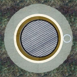
Williams MCP I – PTI Class II Anchor
Two barriers around plain bar in free-stress zone plus drill hole grout.
- Plain or epoxy coated bar
- Smooth PVC sleeve over bar in free-stressing zone
- Grease/wax gel or grout filled smooth PVC sleeve over bar in the free-stress zone
- Unit is centered in drill hole grout with centralizers
- Typically made with 150 KSI All-Thread-Bar or Grade 75 All-Thread Rebar
| Bar Diameter |
Minimum Drill Hole Diameter |
Common Drill Hole Diameter Range |
|---|---|---|
| 1” (26 mm) |
3-1/2” (89 mm) |
3-1/2” to 5” (89 to 127 mm) |
| 1-1/4” (32 mm) |
3-1/2” (89 mm) |
3-1/2” to 5” (89 to 127 mm) |
| 1-3/8” (36 mm) |
4” (102 mm) |
4” to 6” (102 to 152 mm) |
| 1-3/4” (45 mm) |
4-1/2” (114 mm) |
4-1/2” to 7” (114 to 178 mm) |
| 2-1/4” (57 mm) |
5” (127 mm) |
5” to 8” (127 to 203 mm) |
| 2-1/2” (65 mm) |
5” (127 mm) |
5” to 8” (127 to 203 mm) |
| 3” (75 mm) |
6” (152 mm) |
6” to 8” (152 to 203 mm) |
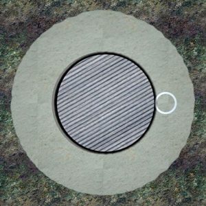
Williams MCP II – PTI Class I Anchor
Two barriers around plain bar full length plus drill hole grout.
- Bar engulfed in pre-grouted poly corrugated tube in the bond anchorage zone
- Smooth PVC sleeve over bar in free-stressing zone
- Grease/wax gel or grout filled smooth PVC sleeve over bar in the free-stress zone
- Unit is centered in drill hole by centralizers and surrounded by grout
| Bar Diameter |
Minimum Drill Hole Diameter |
Common Drill Hole Diameter Range |
|---|---|---|
| 1” (26 mm) |
3-1/2” (89 mm) |
3-1/2” to 5” (89 to 127 mm) |
| 1-1/4” (32 mm) |
3-1/2” (89 mm) |
3-1/2” to 5” (89 to 127 mm) |
| 1-3/8” (36 mm) |
4” (102 mm) |
4” to 6” (102 to 152 mm) |
| 1-3/4” (45 mm) |
5” (127 mm) |
5” to 7” (127 to 178 mm) |
| 2-1/4” (57 mm) |
5” (127 mm) |
5” to 8” (127 to 203 mm) |
| 2-1/2” (65 mm) |
5” (127 mm) |
5” to 8” (127 to 203 mm) |
| 3” (75 mm) |
6” (152 mm) |
6” to 8” (152 to 203 mm) |
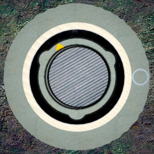
Williams MCP III – PTI Class I Anchor
Three barriers around plain bar in free-stress zone, two barriers in bond zone, plus drill hole grout.
- Bar engulfed in pre-grouted poly corrugated tube in the bond anchorage zone and the free-stressing zone.
- Smooth PVC sleeve over the corrugated tube in the free-stressing zone
- Unit is centered in drill hole by centralizer and surrounded by grout
- Plain or galvanized plate with a welded trumpet
- Protective end cap over nut and washer
| Bar Diameter |
Minimum Drill Hole Diameter |
Common Drill Hole Diameter Range |
|---|---|---|
| 1” (26 mm) |
4-1/2” (114 mm) |
4-1/2” to 6” (114 to 152 mm) |
| 1-1/4” (32 mm) |
4-1/2” (114 mm) |
4-1/2” to 6” (114 to 152 mm) |
| 1-3/8” (36 mm) |
4-1/2” (114 mm) |
4-1/2” to 6” (114 to 152 mm) |
| 1-3/4” (45 mm) |
7” (178 mm) |
7” to 8” (178 to 203 mm) |
| 2-1/4” (57 mm) |
8” (204 mm) |
8” to 10” (203 to 254 mm) |
| 2-1/2” (65 mm) |
8” (204 mm) |
8” to 10” (203 to 254 mm) |
| 3” (75 mm) |
8” (204 mm) |
8” to 10” (203 to 254 mm) |

