Hollow Injection Bar

B7X1 Domestic Hollow Injection Bar
| Bar Diameter |
Average Inner Diameter |
Minimum Net Area Through Threads |
Minimum Ultimate Strength |
Minimum Yield Strength |
Nominal Weight |
Part Number |
|---|---|---|---|---|---|---|
| 32 mm (1-1/4”) |
0.787” (20.0 mm) |
0.556 in² (359 mm²) |
58.4 kips (260 kN) |
47.2 kips (210 kN) |
2.1 lbs/ft (3.1 kg/m) |
B7X1-032N |
| 32S mm (1-1/4”) |
0.626” (15.9 mm) |
0.776 in² (501 mm²) |
81.5 kips (363 kN) |
66.0 kips (294 kN) |
2.7 lbs/ft (4.0 kg/m) |
B7X1-032S |
| 38 mm (1-1/2”) |
0.830” (21.1 mm) |
1.067 in² (688 mm²) |
112 kips (498 kN) |
90.7 kips (404 kN) |
3.76 lbs/ft (5.6 kg/m) |
B7X1-038N |
| 51 mm (2”) |
1.187” (30.1 mm) |
1.795 in² (1158 mm²) |
188 kips (837 kN) |
152 kips (677 kN) |
6.26 lbs/ft (9.3 kg/m) |
B7X1-051N |
| 76 mm (3”) |
1.890” (48.0 mm) |
3.880 in² (2503 mm²) |
407 kips (1811 kN) |
329 kips (1466 kN) |
13.79 lbs/ft (20.5 kg/m) |
B7X1-076N |
Structural Properties
| Yield Stress |
Ultimate Stress |
Minimum Elongation |
|---|---|---|
| 85 KSI (586 MPa) |
105 KSI (724 MPa) |
15% |
B7Y1 Non-Domestic Hollow Injection Bar
| Bar Designation & Outer Diameter |
Average Inner Diameter |
Minimum Net Area Through Threads |
Minimum Ultimate Strength |
Minimum Yield Strength |
Nominal Weight |
Part Number |
|---|---|---|---|---|---|---|
| T30S – 30 mm (1.18”) |
11 mm (0.43”) |
0.662 in2 (427 mm2) |
71.9 kips (320 kN) |
58.5 kips (260 kN) |
2.42 lbs/ft (3.6 kg/m) |
B7Y1-030S |
| T40N – 40 mm (1.57”) |
20 mm (0.79”) |
1.046 in2 (675 mm2) |
121 kips (539 kN) |
96.7 kips (430 kN) |
4.23 lbs/ft (6.3 kg/m) |
B7Y1-040N |
| T40S – 40 mm (1.57”) |
16 mm (0.63”) |
1.222 in2 (788 mm2) |
148 kips (660 kN) |
118 kips (525 kN) |
4.84 lbs/ft (7.2 kg/m) |
B7Y1-040S |
| T52N – 52 mm (2.05”) |
24 mm (0.94”) |
1.874 in2 (1209 mm2) |
209 kips (929 kN) |
164 kips (730 kN) |
6.92 lbs/ft (10.3 kg/m) |
B7Y1-052N |
| T64 – 64 mm (2.52”) |
40 mm (1.57”) |
2.4 in2 (1548 mm2) |
261 kips (1160 kN) |
209 kips (930 kN) |
8.74 lbs/ft (13 kg/m) |
B7Y1-064N |
| * T73N – 73 mm (2.87”) |
53 mm (2.08”) |
2.5 in2 (1615 mm2) |
260 kips (1160 kN) |
218 kips (970 kN) |
8.9 lbs/ft (13.2 kg/m) |
B7Y1-073N * |
| T76S – 76 mm (2.99”) |
45 mm (1.77”) |
3.891 in2 (2510 mm2) |
427 kips (1900 kN) |
337 kips (1500 kN) |
13.23 lbs/ft (19.7 kg/m) |
B7Y1-076S |
| * T103N – 103 mm (4.06”) |
78 mm (3.07”) |
4.87 in2 (3140 mm2) |
510 kips (2270 kN) |
405 kips (1800 kN) |
17.0 lbs/ft (25.3 kg/m) |
B7Y1-103N * |
| * T130N – 130 mm (5.12”) |
60 mm (2.36”) |
16.2 in2 (10452 mm2) |
1785 kips (7940 kN) |
1180 kips (5250 kN) |
50.4 lbs/ft (78 kg/m) |
B7Y1-130N * |
* Diameter available on special order. Contact your Williams representative for fastener and drill bit information.
Hollow Injection Bar Accessories
Stop-Type Couplings
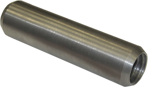
The Domestic Hollow Injection Bar Couplings have a unique tapered center stop which seals the Injection Bar connection to minimize grout leakage during simultaneous grouting and drilling operations. The internal stop design also assures a full positive thread connection in both Injection Bar ends while providing a matching end bearing between bars that reduces percussion energy loss to the drill bit. The couplings provide 100% ultimate tensile or compression strength capacity of the installed anchorage. The coupling OD is tapered on both ends to allow drill cuttings and grout displacement during drilling while the ID has internal chamfers to assist alignment and connection of the bars. The Non-Domestic Hollow Injection Bar Couplings do not contain a tapered center stop, but instead have an o-ring gasket to minimize grout leakage.
| Bar | Outside Diameter |
Overall Length |
Part Number |
|---|---|---|---|
| 32 mm | 1-5/8” (41 mm) |
6-1/4” (159 mm) |
B7X2-32 |
| 38 mm | 2” (51 mm) |
7-5/8” (194 mm) |
B7X2-38 |
| 51 mm | 2-5/8” (67 mm) |
8-1/2” (216 mm) |
B7X2-51 |
| 76 mm | 3-7/8” (98 mm) |
9-7/8” (251 mm) |
B7X2-76 |
| T30 | 1-1/2” (38 mm) |
4-1/8” (105 mm) |
B7Y2-30 |
| T40 | 2-1/8” (54 mm) |
5-1/2” (140 mm) |
B7Y2-40 |
| T52 | 2-3/4” (70 mm) |
6-1/4” (159 mm) |
B7Y2-52 |
| T64 | 3.15” (80 mm) |
7.09” (180 mm) |
B7Y2-064 |
| T76 | 3-3/4” (95 mm) |
8-5/8” (219 mm) |
B7Y2-76 |
Hex Nuts
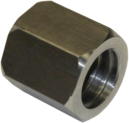
The Hex Nuts designed exclusively for the Geo-Drill Injection Anchor system are a full 100% ultimate tension or compression strength component.
| Nominal Bar Diameter |
Across Flats |
Across Corners |
Thickness | Part Number |
|---|---|---|---|---|
| 32 mm (1-1/4”) |
1-3/4” (44 mm) |
2.0” (51 mm) |
1-3/4” (44 mm) |
B7X3-32 |
| 38 mm (1-1/2”) |
2” (51 mm) |
2.3” (59 mm) |
2” (51 mm) |
B7X3-38 |
| 51 mm (2”) |
3” (76 mm) |
3.5” (88 mm) |
3-1/2” (89 mm) |
B7X3-51 |
| 76 mm (3”) |
4-1/4” (108 mm) |
4.9” (125 mm) |
3-3/4” (95 mm) |
B7X3-76 |
| T30 | 1-7/8” (46 mm) |
2.2” (59 mm) |
1-3/8” (51 mm) |
B7Y3-30 |
| T40 | 2-1/2” (65 mm) |
2.9” (73 mm) |
2” (51 mm) |
B7Y3-40 |
| T52 | 3-1/8” (80 mm) |
3.6” (92 mm) |
2-3/4” (70 mm) |
B7Y3-52 |
| T64 | 3.35” (85 mm) |
3.9” (99 mm) |
2.76” (70 mm) |
B7Y3-064 |
| T76 | 4” (102 mm) |
4.6” (117 mm) |
3-1/8” (80 mm) |
B7Y3-76 |
R8M Beveled Washers
| Bar | Degree of Bevel |
Outside Diameter |
Inside Diameter |
Maximum Thickness |
Minimum Thickness |
Part Number |
|---|---|---|---|---|---|---|
| 32 mm & T30 |
15° | 2-13/16” (71 mm) |
1-5/16” (33 mm) |
1” (25 mm) |
5/16” (8 mm) |
R8M-09S |
| 38 mm | 15° | 3-3/8” (86 mm) |
1-3/4” (44 mm) |
1-1/4” (32 mm) |
3/8” (9.5 mm) |
R8M-12S |
| T40 | 15° | 3-1/2” (89 mm) |
2” (51 mm) |
1-1/4” (32 mm) |
3/8” (9.5 mm) |
R8M-13S |
| 51 mm & T52 |
15° | 5-1/4” (133 mm) |
2-9/32” (58 mm) |
1-5/8” (41 mm) |
7/16” (11 mm) |
R8M-16-150 |
| T64 | 10° | 5-1/2” (140 mm) |
3” (76 mm) |
1-23/32” (44 mm) |
3/4” (19 mm) |
R8M-20 |
| 76 mm & T76 |
15° | 6” (152 mm) |
3-1/2” (89 mm) |
2-7/64” (54 mm) |
1/2” (13 mm) |
R8M-24B7X |
To achieve full strength of the system, beveled washers must be used in conjunction with a hardened washer
R9F Hardened Washers
| Bar | Outside Diameter |
Inside Diameter |
Thickness | Part Number |
|---|---|---|---|---|
| 32 mm & T30 |
2-1/2” (64 mm) |
1-3/8” (35 mm) |
5/32” (4 mm) |
R9F-10-436 |
| 38 mm & T40 |
3” (76 mm) |
1-5/8” (41 mm) |
5/32” (4 mm) |
R9F-12-436 |
| 51 mm & T52 |
3-3/4” (95 mm) |
2-1/8” (54 mm) |
7/32” (5.5 mm) |
R9F-16-436 |
| T64 | 4-1/2” (114 mm) |
2-5/8” (67 mm) |
9/32” (7 mm) |
R9F-20-436 |
| 76 mm & T76 |
5-1/2” (140 mm) |
3-1/8” (80 mm) |
9/32” (7 mm) |
R9F-24-436 |
B7XC Centralizers
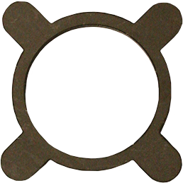
The bar can be centralized in the drill hole on 10’ centers by attaching a steel centralizer in front of the coupling during the drilling operation. Available plain or hot dip galvanized to ASTM A123. State drill hole diameter and bar size when ordering.
B7XB Drill Bits
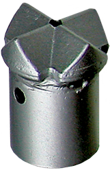 HC Hardened Bit
Hardened cross cut drill bit, suitable for the majority of applications including narrow bands of soft rock.
Soil Types: Fills and Medium Dense Gravels
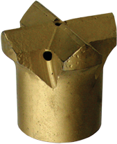 CC Carbide Bit
Tungsten carbide cross-cut drill bit. Excellent choice for majority of granular soils with mixed hard formations.
Soil Types: Fills, Gravels, Shale & Seamy Rock Formations
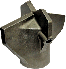 SB Sand/Clay Bit
Two stage cross cut drill bit, suitable for loose to medium dense ground and fills.
Soil Types: Sand, Clay and Light Gravels
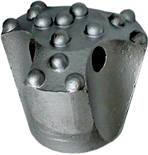
BB Button Bit
Tungsten carbide hemispherical button drill bit for moderately strong to strong rock, boulders and rubble.
Rock Types: Mudstone, Limestone, and Granite
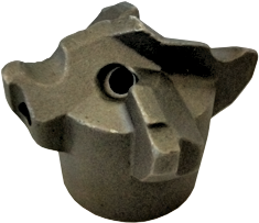 CB Cobble Bit
Offset face cross cut drill bit suitable for drilling in cobbles with silt and gravel as well as sedimentary bedrock material.
| Nominal Bar Diameter |
Available Drill Bit Diameters | ||||
|---|---|---|---|---|---|
| HC | CC | SB | BB | CB | |
| 32 mm | 2” (51 mm) |
2” (51 mm) |
5” (127 mm) |
2-1/2” (65 mm) |
4” (102 mm) |
| 2-1/2” (65 mm) |
2-1/2” (65 mm) |
||||
| 3” (76 mm) |
|||||
| 3” (76 mm) |
3” (76 mm) |
||||
| 3-1/2” (89 mm) |
|||||
| 3-1/2” (89 mm) |
3-1/2” (89 mm) |
||||
| 4” (102 mm) |
|||||
| 4” (102 mm) |
4” (102 mm) |
||||
| 38 mm
T30 T40 |
2-1/2” (65 mm) |
2-1/2” (65 mm) |
5” (127 mm) |
2-1/2” (65 mm) |
4” (102 mm) |
| 3” (76 mm) |
3” (76 mm) |
||||
| 3” (76 mm) |
|||||
| 3-1/2” (89 mm) |
3-1/2” (89 mm) |
||||
| 3-1/2” (89 mm) |
6” (152 mm) |
||||
| 4” (102 mm) |
4” (102 mm) |
||||
| 4” (102 mm) |
|||||
| 4-1/2” (114 mm) |
5” (127 mm) |
||||
| 51 mm | – | 3” (76 mm) |
6” (152 mm) |
3” (76 mm) |
4-3/4” (121 mm) |
| 3-1/2” (90 mm) |
|||||
| 3-1/2” (90 mm) |
|||||
| 4” (102 mm) |
|||||
| 4-1/2” (114 mm) |
8” (203 mm) |
4” (102 mm) |
6” (152 mm) |
||
| 5” (127 mm) |
|||||
| 5” (127 mm) |
|||||
| 6” (152 mm) |
|||||
| T52 | – | 4” (102 mm) |
7” (178 mm) |
– | – |
| T64
76 mm T76 |
– | 5” (125 mm) |
7” (178 mm) |
5” (125 mm) |
– |
| 6” (152 mm) |
|||||
| 10” (254 mm) |
6” (152 mm) |
||||
| 7” (175 mm) |
|||||

