Grade 60 All-Thread Rebar

| Bar Designation Nominal Diameter & Pitch |
Minimum Net Area Thru Threads |
Minimum Ultimate Strength |
Minimum Yield Strength |
Nominal Weight |
Approx. Thread Major Dia. |
Part Number |
|---|---|---|---|---|---|---|
| #4 – 1/2” (13 mm) |
0.2 in2 (129 mm2) |
16 kips (71.2 kN) |
12.0 kips (53.4 kN) |
0.68 lbs/ft (1.0 kg/m) |
5/8” (16 mm) |
R51-04 |
| #5 – 5/8” (16 mm) |
0.32 in2 (206 mm2) |
25.6 kips (114 kN) |
19.2 kips (85.4 kN) |
1.09 lbs/ft (1.6 kg/m) |
3/4” (19 mm) |
R51-05 |
| #6 – 3/4” – 5 (19 mm) |
0.44 in2 (284 mm2) |
35.2 kips (157 kN) |
26.4 kips (117 kN) |
1.5 lbs/ft (2.4 kg/m) |
7/8” (22 mm) |
R51-06 |
| #7 – 7/8” – 5 (22 mm) |
0.60 in2 (387 mm2) |
48.0 kips (214 kN) |
36.0 kips (160 kN) |
2.0 lbs/ft (3.0 kg/m) |
1” (25 mm) |
R51-07 |
| #8 – 1” – 3-1/2 (25 mm) |
0.79 in2 (510 mm2) |
63.2 kips (281 kN) |
47.4 kips (211 kN) |
2.7 lbs/ft (3.9 kg/m) |
1-1/8” (29 mm) |
R51-08 |
Structural Properties
| Minimum Yield |
Ultimate Tensile |
Typical Elongation in 8″ bar |
|---|---|---|
| 60 KSI (413 MPa) |
80 KSI (552 MPa) |
7% min |
Williams All-Thread Grade 60 Rebar is a continuously threaded bendable alternative to traditional rebar. All-Thread-Rebar can be spliced with a mechanical coupling which is capable of developing 100% of the bars tensile capacity.
System Advantages
The Williams All-thread Rebar Splice System allows you to field produce RebarDowel Connections from stock inventory. The ease of producing your own splices simplifies the forming operation and helps meet scheduling deadlines.
- No waiting for custom sizes or lengths
- Easy field assembly
- No special tools required
- Eliminates Protruding Dowels
- No torque requirements
- Stop type coupling ensures proper engagement
- Reduces forming and stripping cost
- Full Strength Splice
System Compliance
The Grade 60 All-Thread Rebar Splice System complies with the following standards and specifications.
- IAPMO Evaluation Report # 0205
- American Concrete Institute (ACI Standard 318)
- 2009 International Building Code (IBC)
- 2009 International Residential Code (IRC)
- State Departments of Transportation
Accessories
R52 Stop-Type Couplings
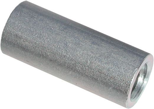
| Bar Desig. & Nominal Dia. |
Outside Diameter |
Overall Length |
Part Number |
|---|---|---|---|
| #4 – 1/2” (13 mm) |
15/16” (24 mm) |
2-1/8” (54 mm) |
R52-04 |
| #5 – 5/8” (16 mm) |
1-1/16” (27 mm) |
2-3/8” (60 mm) |
R52-05 |
| #6 – 3/4” (19 mm) |
1-1/4” (32 mm) |
2-3/4” (70 mm) |
R52-06 |
| #7 – 7/8” (22 mm) |
1-3/8” (35 mm) |
3-1/4” (83 mm) |
R52-07 |
| #8 – 1” (25 mm) |
1-5/8” (41 mm) |
3-7/8” (98 mm) |
R52-08 |
C2DD Flange Coupling
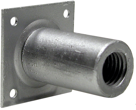
| Bar Desig. & Nominal Dia. |
Outside Diameter |
Coupling Length |
Flange Depth |
Flange Width |
Part Number |
|---|---|---|---|---|---|
| #4 – 1/2” (13 mm) |
15/16” (24 mm) |
2-1/8” (54 mm) |
0.06” (1.6 mm) |
2” (51 mm) |
C2DD-04 |
| #5 – 5/8” (16 mm) |
1-1/16” (27 mm) |
2-3/8” (60 mm) |
0.06” (1.6 mm) |
2” (51 mm) |
C2DD-05 |
| #6 – 3/4” (19 mm) |
1-1/4” (32 mm) |
2-3/4” (70 mm) |
0.06” (1.6 mm) |
2” (51 mm) |
C2DD-06 |
| #7 – 7/8” (22 mm) |
1-3/8” (35 mm) |
3-1/4” (83 mm) |
0.06” (1.6 mm) |
3” (76 mm) |
C2DD-07 |
| #8 – 1” (25 mm) |
1-5/8” (41 mm) |
3-7/8” (98 mm) |
0.06” (1.6 mm) |
3” (76 mm) |
C2DD-08 |
R53 Hex Nuts
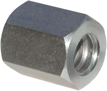
| Bar Desig. & Nominal Dia. |
Across Flats |
Across Corners |
Thickness | Part Number |
|---|---|---|---|---|
| #4 – 1/2” (13 mm) |
15/16” (24 mm) |
1.08” (28 mm) |
5/8” (16m) |
R53-04 |
| #5 – 5/8” (16 mm) |
1-1/16” (27 mm) |
1.23” (31 mm) |
3/4” (19 mm) |
R53-05 |
| #6 – 3/4” (19 mm) |
1-1/4” (32 mm) |
1.44” (37 mm) |
7/8” (22 mm) |
R53-06 |
| #7 – 7/8” (22 mm) |
1-7/16” (37 mm) |
1.66” (42 mm) |
1” (25 mm) |
R53-07 |
| #8 – 1” (25 mm) |
1-5/8” (41 mm) |
1.88” (48 mm) |
1-1/8” (29 mm) |
R53-08 |
R9F Hardened Washers
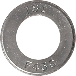
| Bar Desig. & Nominal Dia. |
Outside Diameter |
Inside Diameter |
Thickness | Part Number |
|---|---|---|---|---|
| #4 – 1/2” (13 mm) |
1-5/16” (33 mm) |
11/16” (18mm) |
9/64” (3.6 mm) |
R9F-05-436 |
| #5 – 5/8” (16 mm) |
1-7/16” (37 mm) |
13/16” (21 mm) |
9/64” (3.6 mm) |
R9F-06-436 |
| #6 – 3/4” (19 mm) |
1-3/4” (45 mm) |
15/16” (24 mm) |
5/32” (4 mm) |
R9F-07-436 |
| #7 – 7/8” (22 mm) |
2” (51 mm) |
1-1/16” (29 mm) |
5/32” (4 mm) |
R9F-08-436 |
| #8 – 1” (25 mm) |
2-1/4” (57 mm) |
1-3/16” (30 mm) |
5/32” (4 mm) |
R9F-09-436 |
