![]()
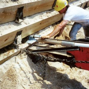
These anchors are intended for use in soil conditions for moderately loaded anchoring requirements. WFEC Soil Anchors use a tipping plate which is dependent upon the strength of the soil in order to react tensile loads. Anchors are driven into soil to a specified depth using special drive steel which is adaptable to percussion driving equipment, (i.e. jackhammer, concrete breaker or similar). The drive steel is removed and the anchor is tipped into place and proof tested with Williams’ Anchor Locking Kit by pulling on the anchor rod. This is called “load locking” and provides an immediate proof test of each anchor’s holding capacity. Interested customers should contact their local Williams technical representative in order to evaluate the appropriate anchor for each specific project.
Advantages
- Fast, easy installation
- Immediate proof test results
- No grout
- Inexpensive installation equipment
- Environmentally friendly
- No drilling required
Applications
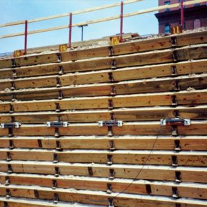
- Retaining Walls
- Slope Stabilization
- Bridges
- Sheet Piling
- Gabion Support
- Buoyancy Control
- Guyed Structures
- Scaffolding
- Foundations
- Portable Buildings
- General Security
- Marine Applications
- Temporary Shoring
- Utility Poles
- Seawalls
- Pipelines
- Erosion Control
- Underwater Applications
Manta Ray Earth Anchors are available in a variety of sizes and are perfectly matched to Williams #6 Grade 75 galvanized All-Thread Rebar to achieve working loads up to 20,000 lbs. The galvanized, cast ductile-iron Manta Ray Anchors utilize a secured, pivoting shackle tapped with Williams’ All-Thread Rebar thread pattern in order to transfer tensile loads. The robust, course thread pattern is extremely durable during anchor driving and eliminates the concern for thread chasing often required when using NC thread pattern anchor rods.
The Manta Ray system provides a holding capacity chart that should be used for estimation purposes in order to select the appropriate Manta Ray model for your specific loading and soil conditions. Williams Form Engineering recommends a field test of anchor strength prior to anchor ordering whenever possible.
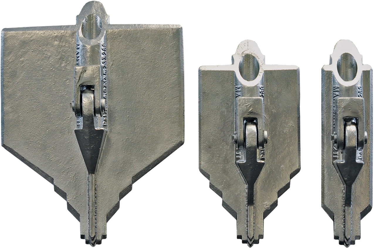
There are six Manta Ray Anchors with light to heavy duty holding capacities. All anchors are made of galvanized ductile iron, can be driven with the drive steel set and can be tested to the desired holding capacity with the load locker. The anchors are designed to utilize solid steel rods as load carrying members.
Manta Ray Anchor Structural Properties
| Manta Ray Anchor |
Max Safe Working Load (2:1 FS) |
Anchor Rod | Weight per Each |
|
|---|---|---|---|---|
| Diameter | Part Number |
|||
| MR-68 | 2.5 kips (11 kN) |
3/8” (10 mm) |
B8S-03 | 1 lbs (0.5 kg) |
| MR-88 | 5 kips (22 kN) |
1/2” (12 mm) |
B8S-04 | 2.1 lbs (1 kg) |
| MR-3 | 10 kips (45 kN) |
#6 – 3/4” (20 mm) |
R61-06 | 7 lbs (3.2 kg) |
| MR-2 | 20 kips (89 kN) |
#6 – 3/4” (20 mm) |
R61-06 | 12 lbs (5.4 kg) |
| MR-1 | 20 kips (89 kN) |
#6 – 3/4” (20 mm) |
R61-06 | 14 lbs (6.4 kg) |
| MR-SR | 20 kips (89 kN) |
#6 – 3/4” (20 mm) |
R61-06 | 22 lbs (10 kg) |
Williams Anchor Rods are fully threaded and can be field cut and coupled.
Anchor rod lengths:
R61 up to 50 feet uncoated
B8S up to 20 feet
Galvanized rods should be cut to size prior to galvanizing to insure good nut fit.
Manta Ray Working Capacities in Listed Soils
| Common Soil Type Description |
Typical Blow Count “N” per ASTM D1586 |
MR-68 | MR-88 | MR-3 | MR-2 | MR-1 | MR-SR |
|---|---|---|---|---|---|---|---|
| Very dense/cemented sands; coarse gravel and cobbles |
60 – 100+ | 2.5 kips (1, 3) |
5 kips (1, 3) |
10 kips (1, 3) |
20 kips (1, 3) |
(5) | (5) |
| Dense fine sand; very hard silts and clays |
45 – 60 | 1.5-2 kips (2, 3, 4) |
4-5 kips (2, 3, 4) |
8.5-10 kips (2, 3, 4) |
10.5-14 kips (2, 4) |
18-20 kips (1, 3, 4) |
20 kips (1, 3) |
| Dense clays, sands and gravel; hard slits and clays |
35 – 50 | 1.1-1.5 kips (4) |
2-3 kips (4) |
6-9 kips (2, 4) |
7.5-11 kips (2, 4) |
12-18 kips (2, 4) |
16-20 kips (2, 3, 4) |
| Medium dense sandy gravel; very stiff to hard silts and clays |
24 – 40 | 0.75-1 kips (4) |
1.5-2 kips (4) |
4.5-7 kips (4) |
6-9 kips (4) |
9-10 kips (2, 4) |
12-17 kips (2, 4) |
| Medium dense coarse sand and sandy gravel; stiff to very stiff silts and clays |
14 – 25 | 0.55-0.75 kips (4) |
1-1.5 kips (4) |
3.5-4.5 kips (4) |
4.5-6 kips (4) |
7.5-10 kips (4) |
9-12 kips (4) |
| Loose to medium dense fine to coarse sand; firm to stiff clays and silts |
7 – 14 | 0.45-0.6 kips (4) |
0.75-1.25 kips (4) |
2.5-4 kips (4) |
3.5-5 kips (4) |
5-7.5 kips (4) |
7-9 kips (4) |
| Loose fine sand; alluvium; soft-firm clays; varied clays; fills |
4 – 8 | 0.3-0.5 kips (4, 6) |
0.45-0.75 kips (4, 6) |
1.5-2.5 kips (4, 6) |
2.5-4 kips (4, 6) |
4-6 kips (4, 6) |
4.5-7 kips (4, 6) |
| Peat, organic silts; inundates silts fly ash |
0 – 5 | (5) | 0.1-0.45 kips (4, 6) |
0.4-1.5 kips (4, 6) |
1-2.5 kips (4, 6) |
1.5-4 kips (4, 6) |
2-6 kips (4, 6) |
1 – Drilled hole required to install.
2- Installation may be difficult. Pilot hole may be required.
3- Holding capacity limited by max safe working load of anchors.
4- Holding capacity limited by soil strength.
5- Not recommended in these soils.
6- Wide variation in soil properties reduces prediction accuracy
Use this chart for estimation only, true capacity must be tested with anchor locker. The values in chart are based on minimum 3’ embedment depth for models MR-68 & MR-88 and 7’ for Models MR-3 thru MR-SR. (Minimum overburden depth is 4’.) Field testing is recommended for other possible depths.
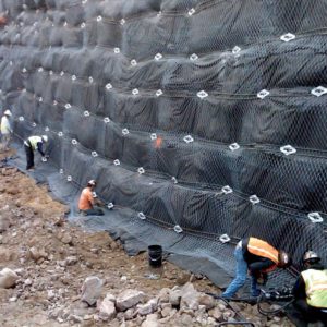
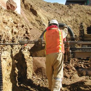
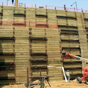
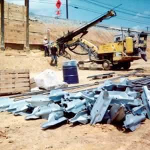
Project Photos