150 KSI-All-Thread Bar

| Nominal Bar Diameter & Pitch |
Minimum Net Area Thru Threads |
Minimum Ultimate Strength |
Prestressing Force | Nominal Weight |
Approx. Thread Major Dia. |
Part Number |
||
|---|---|---|---|---|---|---|---|---|
| 0.80f pu A | 0.70f pu A | 0.60f pu A | ||||||
| 1” – 4 (26 mm) |
0.85 in2 (549 mm2) |
128 kips (567 kN) |
102 kips (454 kN) |
89.3 kips (397 kN) |
76.5 kips (340 kN) |
3.09 lbs/ft (4.6 kg/m) |
1-1/8” (29 mm) |
R71-08 |
| 1-1/4” – 4 (32 mm) |
1.25 in2 (807 mm2) |
188 kips (834 kN) |
150 kips (667 kN) |
131 kips (584 kN) |
113 kips (500 kN) |
4.51 lbs/ft (6.7 kg/m) |
1-7/16” (37 mm) |
R71-10 |
| 1-3/8” – 4 (36 mm) |
1.58 in2 (1019 mm2) |
237 kips (1054 kN) |
190 kips (843 kN) |
166 kips (738 kN) |
142 kips (633 kN) |
5.71 lbs/ft (8.5 kg/m) |
1-9/16” (40 mm) |
R71-11 |
| 1-3/4” – 3-1/2 (46 mm) |
2.60 in2 (1664 mm2) |
390 kips (1734 kN) |
312 kips (1388 kN) |
273 kips (1214 kN) |
234 kips (1041 kN) |
9.06 lbs/ft (13.5 kg/m) |
2” (51 mm) |
R71-14 |
| 2-1/4” – 3-1/2 (57 mm) |
4.08 in2 (2632 mm2) |
613 kips (2727 kN) |
490 kips (2181 kN) |
429 kips (1909 kN) |
368 kips (1636 kN) |
14.1 lbs/ft (20.8 kg/m) |
2-1/2” (64 mm) |
R71-18 |
| 2-1/2” – 3 (65 mm) |
5.19 in2 (3350 mm2) |
778 kips (3457 kN) |
622 kips (2766 kN) |
545 kips (2422 kN) |
467 kips (2074 kN) |
18.2 lbs/ft (27.1 kg/m) |
2-3/4” (70 mm) |
R71-20 |
| 3” – 3 (75 mm) |
6.85 in2 (4419 mm2) |
1027 kips (4568 kN) |
822 kips (3656 kN) |
719 kips (3198 kN) |
616 kips (2740 kN) |
24.1 lbs/ft (35.8 kg/m) |
3-1/8” (80 mm) |
R71-24 |
Structural Properties
| Yield Stress |
Ultimate Stress |
Elongation in 20 bar diameters |
Reduction of Area |
|---|---|---|---|
| 120 KSI (827 MPa) |
150 KSI (1034 MPa) |
4% | 20% min. |
Steel Quality
Williams 1” through 1-3/4” 150 KSI bars are widely available as cold-stressed and stress relieved in strict compliance with ASTM A722 and AASHTO M275 Highway Specifications. While the 2-1/4” through 3” 150 KSI bars are exclusively available as alloy steel that is quenched and tempered to meet the prescribed tensile properties of ASTM A722, all sizes are available and occasionally supplied using this process.
Thorough inspection and traceability are carried out during all phases of manufacturing to assure the highest standards of quality.
Properties
Williams 150 KSI bars are manufactured in 7 diameters from 1” (26 mm) through 3” (75 mm). All diameters are available in continuous lengths up to 50’ (15.2 m).
Williams 150 KSI bars are high in strength yet ductile enough to exceed the specified elongation and reduction of area requirements. Selected heats can also pass the 135° supplemental bend test when required. Testing has shown Williams 150 KSI All-Thread-Bars to meet or exceed post tensioning bar and rock anchoring criteria as set by the Post Tensioning Institute including dynamic test requirements beyond 500,000 cycles of loading.
Tensile Strength & Working Loads
Per PTI recommendations for anchoring, anchors should be designed so that the design load is not more than 60% of the specified minimum tensile strength of the prestressing steel. The lock-off load should not exceed 70% of the specified minimum tensile strength of the prestressing steel. The maximum test load should not exceed 80% of the specified minimum tensile strength of the prestressing steel. The maximum test load and the maximum factored design load must not exceed the yield strength of ANY steel element.
Threads
All-Thread-Bars are cold rolled threaded to close tolerances under continuous monitoring procedures for quality control. Threads for Williams 150 KSI bar are specially designed with a rugged thread pitch wide enough to be fast under job site conditions and easy to assemble. They also have a smooth, wide, concentric, surface suitable for torque tensioning. This combination offers tremendous installation savings over inefficient, hot rolled, non-concentric thread forms. Threads are standard left-hand for diameters up to 1-3/8” and right-hand for diameters over 1-3/4”, with any direction available on special request.
Williams All-Thread-Bars are threaded around the full circumference enabling the load transfer from the bar to the fasteners to occur efficiently without eccentric point loading. Williams fasteners easily meet the allowable load transfer limitations set forth by the Post Tensioning Institute. Williams 150 KSI All-Thread-Bars and fasteners are machined to tight tolerances for superior performance and mechanical lock. Precision machining greatly reduces concern of fastener loosening or detensioning. Williams 150 KSI bars exceed the deformation requirements of ASTM A722. Williams special thread deformation pattern projects ultra high relative rib area, much greater than conventional rebar. This provides for superior bond performance in grout or concrete.
Cutting (No Welding)
Williams 150 KSI All-Thread-Bar should not be subjected to the heat of a torch, welding or used as a ground. Field cutting should be done with an abrasive wheel or band saw.
Stress Relaxation
Currently ASTM A722 does not include prescribed maximum relaxation thresholds. However, Williams can provide 150 KSI bars that meet project specific relaxation values. Consult your WFEC rep for more information.
Shear
ACI 318-14, Section 17.5.1.2 indicates that the nominal shear strength of an anchor not exceed 0.60 x area of steel x the ultimate strength of the steel. Designers should utilize appropriate resistance factors for shear based on the condition of use.
150 KSI All-Thread-Bar Accessories
All Couplings and Hex/Collar Nuts exceed 100% of the bar’s published ultimate strength and couplings will meet ACI 318 Section 25.5.7.1 for mechanical rebar connections.
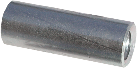
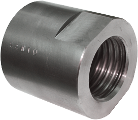
R72 Stop-Type Couplings
| Bar Diameter |
Outside Diameter |
Overall Length |
Part Number |
|---|---|---|---|
| 1” (26 mm) |
1-3/4” (44 mm) |
4” (102 mm) |
R72-08 |
| 1-1/4” (32 mm) |
2-1/8” (54 mm) |
4-1/2” (114 mm) |
R72-10 |
| 1-3/8” (36 mm) |
2-3/8” (60 mm) |
5” (127 mm) |
R72-11 |
| 1-3/4” (46 mm) |
3” (76 mm) |
8-1/2” (216 mm) |
R72-14 |
| 2-1/4” (57 mm) |
3-1/2” (89 mm) |
8-1/2” (216 mm) |
R72-18 |
| 2-1/2” (65 mm) |
4-1/4” (108 mm) |
8-5/8” (219 mm) |
R72-20 |
| 3” (75 mm) |
5” (127 mm) |
11-7/8” (302 mm) |
R72-24 |
Couplings are available as tap thru upon request
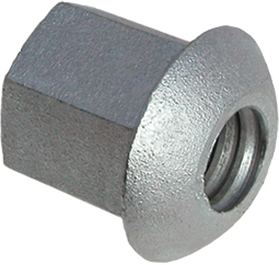
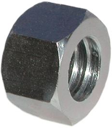
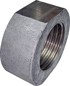
R73 Hex Nuts / R74 Collar Nuts
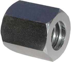
Hex Nut Rounded Collar Nut
| Bar Diameter |
Across Flats |
OD/Across Corners |
Thickness | Part Number |
|---|---|---|---|---|
| 1” (26 mm) |
1-3/4” (44 mm) |
2.0” (51 mm) |
1-5/8” (41 mm) |
R73-08 |
| 1-1/4” (32 mm) |
2-1/4” (57 mm) |
2.6” (66 mm) |
1-7/8” (48 mm) |
R73-10 |
| 1-3/8” (36 mm) |
2-1/2” (64 mm) |
2.9” (73 mm) |
2-1/8” (54 mm) |
R73-11 |
| 1-3/4” (46 mm) |
3” (76 mm) |
3.5” (88 mm) |
3-1/2” (89 mm) |
R73-14 |
| 2-1/4” (57 mm) |
3-3/4” (95 mm) |
4.3” (109 mm) |
3-3/4” (95 mm) |
R73-18 |
| 2-1/2” (65 mm) |
4-1/4” (108 mm) |
4.9” (124 mm) |
3-3/4” (95 mm) |
R73-20 |
| 3” * (75 mm) |
4-1/2” (114 mm) |
OD 5” (127 mm) |
5-1/2” (140 mm) |
R74-24 |
* Rounded Collar Nut
R88 Spherical Hex Huts
Provides up to 5 ̊ angle when used with a dished plate
| Bar Diameter |
Across Flats |
Thickness | Outside Dome |
Part Number |
|---|---|---|---|---|
| 1” (26 mm) |
1-3/4” (44 mm) |
2-1/4” (57 mm) |
2-1/2” (64 mm) |
R88-08 |
| 1-1/4” (32 mm) |
2-1/4” (57 mm) |
2-3/4” (70 mm) |
3-1/8” (80 mm) |
R88-10 |
| 1-3/8” (36 mm) |
2-1/2” (64 mm) |
3-1/4” (83 mm) |
3-5/8” (90 mm) |
R88-11 |
| 1-3/4” (46 mm) |
3” (76 mm) |
3-1/2” (89 mm) |
4” (102 mm) |
R88-14 |
| 2-1/4” * (57 mm) |
3-3/4” (95 mm) |
5-1/4” (133 mm) |
5-1/2” (140 mm) |
R73-18 R81-18 |
| 2-1/2” * (65 mm) |
4-1/4” (108 mm) |
5-1/2” (140 mm) |
6” (152 mm) |
R73-20 R81-20 |
| 3” ** (75 mm) |
4-1/4” (108 mm) |
7-1/2” (191 mm) |
7” (178 mm) |
R74-24 R81-24 |
* Standard Nut with Spherical Washer assembly
** Rounded Collar Nut with Spherical Washer assembly
R73/R74-JN Jam Nuts
Hex Jam Nut Rounded Collar Jam Nut
Jam Nuts can not be substituted for full strength nuts. Larger diameters will be a rounded collar jam nut, with special order machined hex available.
| Bar Diameter |
Across Flats |
OD/Across Corners |
Thickness | Part Number |
|---|---|---|---|---|
| 1” (26 mm) |
1-3/4” (44 mm) |
2” (51 mm) |
0.41” (10 mm) |
R73-08JN |
| 1-1/4” * (32 mm) |
1-7/8” (48 mm) |
OD 2-1/8” (54 mm) |
0.47” (12 mm) |
R73-10JN |
| 1-3/8” * (36 mm) |
2-1/8” (54 mm) |
OD 2-3/8” (60 mm) |
0.53” (14 mm) |
R73-11JN |
| 1-3/4” * (46 mm) |
2-3/4” (70 mm) |
OD 3” (76 mm) |
0.88” (22 mm) |
R73-14JN |
| 2-1/4”* (57 mm) |
3-1/4” (83 mm) |
OD 3-1/2” (89 mm) |
0.94” (24 mm) |
R73-18JN |
| 2-1/2” * (65 mm) |
4” (102 mm) |
OD 4-1/4” (108 mm) |
0.94” (24 mm) |
R73-20JN |
| 3” * (75 mm) |
4-1/2” (114 mm) |
OD 5” (127 mm) |
1.38” (35 mm) |
R74-24JN |
*Round Collar Jam Nut
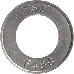
R9F Hardened Washers
| Bar Diameter |
Outside Diameter |
Inside Diameter |
Thickness | Part Number |
|---|---|---|---|---|
| 1” (26 mm) |
2-1/4” (57 mm) |
1-3/16” (30 mm) |
5/32” (4 mm) |
R9F-09-436 |
| 1-1/4” (32 mm) |
2-3/4” (70 mm) |
1-1/2” (38 mm) |
5/32” (4 mm) |
R9F-11-436 |
| 1-3/8” (36 mm) |
3” (76.2 mm) |
1-5/8” (41 mm) |
5/32” (4 mm) |
R9F-12-436 |
| 1-3/4” (46 mm) |
3-3/4” (95 mm) |
2-1/8” (54 mm) |
7/32” (6 mm) |
R9F-16-436 |
| 2-1/4” (57 mm) |
4-1/2” (114 mm) |
2-5/8” (67 mm) |
9/32” (7 mm) |
R9F-20-436 |
| 2-1/2” (65 mm) |
5” (127 mm) |
2-7/8” (73 mm) |
9/32” (7 mm) |
R9F-22-436 |
| 3” (75 mm) |
6” (152 mm) |
3-3/8” (86 mm) |
9/32” (7 mm) |
R9F-26-436 |
To achieve full strength of the system, hardened washers must be used with R73 hex nuts
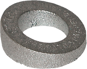
R8M Beveled Washers
| Bar Diameter |
Degree of Bevel |
Outside Diameter |
Inside Diameter |
Maximum Thickness |
Minimum Thickness |
Part Number |
|---|---|---|---|---|---|---|
| 1” (26 mm) |
10° | 2-27/32” (72 mm) |
1-7/16” (37 mm) |
7/8” (22 mm) |
3/8” (10 mm) |
R8M-08-10 |
| 1-1/4” * (32 mm) |
15° | 3-3/8” (86 mm) |
1-9/16” (40 mm) |
1-1/4” (32 mm) |
3/8” (10 mm) |
R8M-12-15 |
| 1-3/8” * (36 mm) |
15° | 3-1/2” (89 mm) |
1-3/4” (44 mm) |
1-1/4” (32 mm) |
3/8” (10 mm) |
R8M-13-15 |
| 1-3/4” (46 mm) |
15° | 5-1/4” (133 mm) |
2-1/4” (57 mm) |
1-5/8” (41 mm) |
3/8” (10 mm) |
R8M-16-15 |
| 2-1/4” (57 mm) |
10° | 6-1/2” (165 mm) |
3” (76 mm) |
1-7/8” (48 mm) |
3/4” (19 mm) |
R8M-18-10 |
| 2-1/2” (65 mm) |
10° | 7-1/2” (190 mm) |
3-1/2” (89 mm) |
2-5/16” (59 mm) |
1” (25 mm) |
R8M-21-10 |
| 3” * (75 mm) |
10° | 8” (203 mm) |
3-5/8” (92 mm) |
2-7/16” (62 mm) |
1” (25 mm) |
R8M-25-10 |
To achieve full strength of the system, beveled washers must be used in conjunction with a hardened washer.
R74 Terminator

| Bar Diameter |
Thickness | Terminator OD |
Part Number |
|---|---|---|---|
| 1” (26 mm) |
1-5/8” (41 mm) |
3” (76 mm) |
R74-08-DN |
| 1-1/4” (32 mm) |
1-7/8” (48 mm) |
3-3/4” (95 mm) |
R74-10-DN |
| 1-3/8” (36 mm) |
2-1/8” (54 mm) |
4-1/4” (108 mm) |
R74-11-DN |
| 1-3/4” (46 mm) |
3-1/2” (89 mm) |
5-1/4” (133 mm) |
R74-14-DN |
| 2-1/4” (57 mm) |
3-3/4” (95 mm) |
6-3/4” (171 mm) |
R74-88-DN |
Williams threaded terminators offer an economical alternative to the conventional approach of a plate between two hex nuts. With only a single component, they are more efficient to install and reduce congestion around the reinforcement. Since they are used with Williams threaded bars, they can be easily adjusted to the desired location and require no specialized equipment to install unlike other terminator systems.
Williams terminators meet the requirements of ASTM A970 Class HA. The dimensions shown for bar sizes up to #11 (1-3/8”) exceed the requirements of ACI 318-19 Section 25.4.4, so can be used as headed reinforcement to reduce development length of a Williams threaded bar without the need for 90 degree bends or 180 degree hooks. Additionally, the nominal pullout strength of Williams terminators in 3000 psi concrete exceeds the specified tensile strength of the bar per ACI 318-19 Chapter 17. Other failure modes such as concrete breakout and side face blowout should be analyzed by the Engineer of Record.
For larger quantities, contact your Williams Representative to evaluate the cost saving design advantages of higher strength concrete.
