Spin-Lock Concrete Anchor Installation
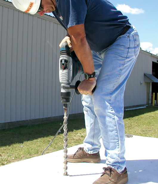
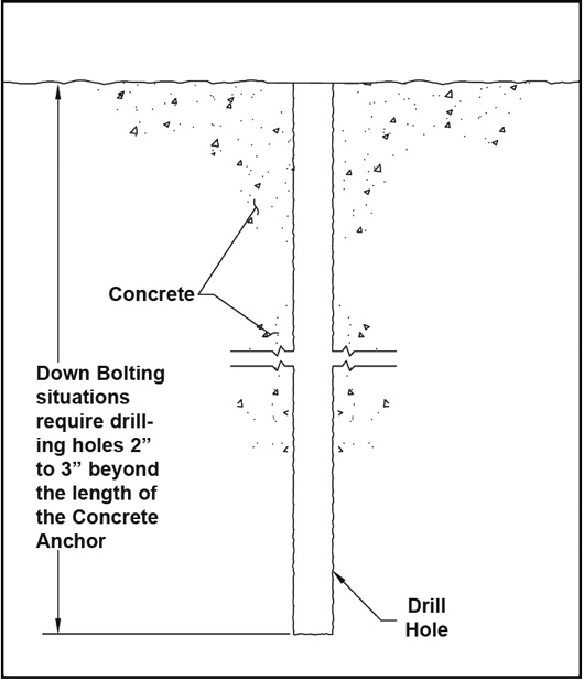
Step 1: Drilling
Use Hammer Drill or Core Drill
Care should be taken to ensure an accurate diameter and the drilled hole is as perpendicular to the concrete surface as possible. The hole depth should be drilled 2” to 3” deeper than the anchor embedment depth. Clean the drill hole by blowing air at the bottom of the hole to remove debris.
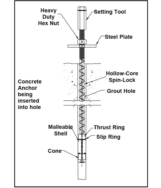
Step 2: Anchor Placement
Place the nut, washer, bevel washers (if required), and plate on the anchor. Insert the anchor into the hole to correct anchor embedment depth. If the anchor becomes stuck in the hole, attach the setting tool to the end of the anchor and drive it into the hole with a hammer. If the anchor slides into the hole extremely loose, remove the anchor from the hole. Pre-expand the anchor head 1/2 revolution or until it fits snugly into the drill hole.
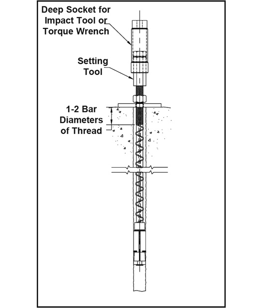
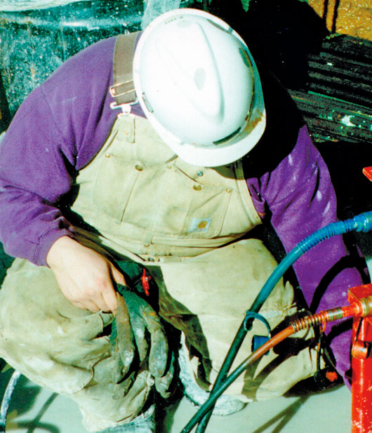
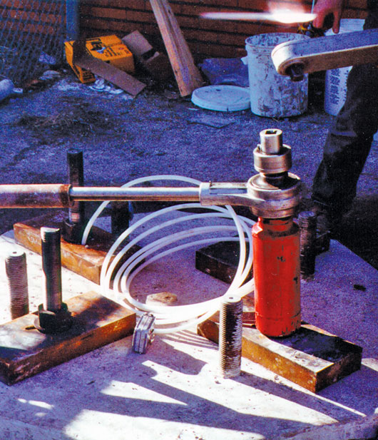
Step 3: Setting the Anchor
Before placing the setting tool on the anchor, it should be inspected to ensure both sections are turned tightly together and the washers are greased. Install setting tool fully onto the exposed threaded end of the anchor. Initially torque the anchor with an impact gun. This action migrates the cone into the shell, thus expanding the mechanical anchor into the concrete. The final torque can be checked and adjusted with a manual or hydraulic torque wrench. Remove the setting tool by restraining the lower section while rotating its upper section counter-clockwise until the setting tool is loose.

Step 4a: Testing the Anchor
Method A: Tensioning with a Test Jack
Place the jack and frame over the anchor and attach the test rod and couplings to the anchor. Make sure the coupling is fully engaged. Attach the test nut and test plate over the test rod on top of the jack. Test the anchor by tensioning the jack to the required test load (usually half of the ultimate strength) but never to exceed the advertised yield strength of the anchor. Adjust the jack to the required final tension and lock in the final prestress load. This is done by tightening the concrete anchor hex nut with a knocker wrench (through the frame opening) until a slight reduction is noticed on the jack gauge. The full prestress load will be transferred to the anchor bolt once the tension in the test jack has been released and test components removed.
Step 4b: Testing the Anchor
Method B: Tensioning by Toque Tensioning
Tension the anchor by torquing the hex nut with a torque wrench. To obtain the advertised tensile working load, seethe “Torque On Nut” column on the Spin-Lock Anchor charts. For other desired loads, see the torque tension graphs shown here. Please Note: The torque/tension relationship is not as accurate as direct tensioning with a hydraulic jack and should not be used where critical tension loads need to be verified.
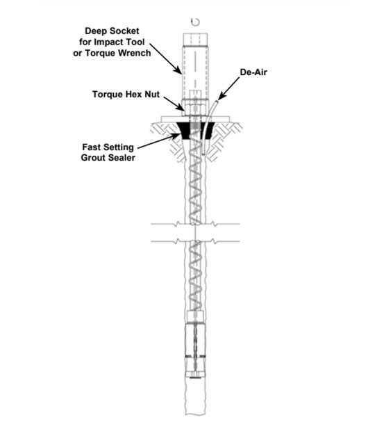
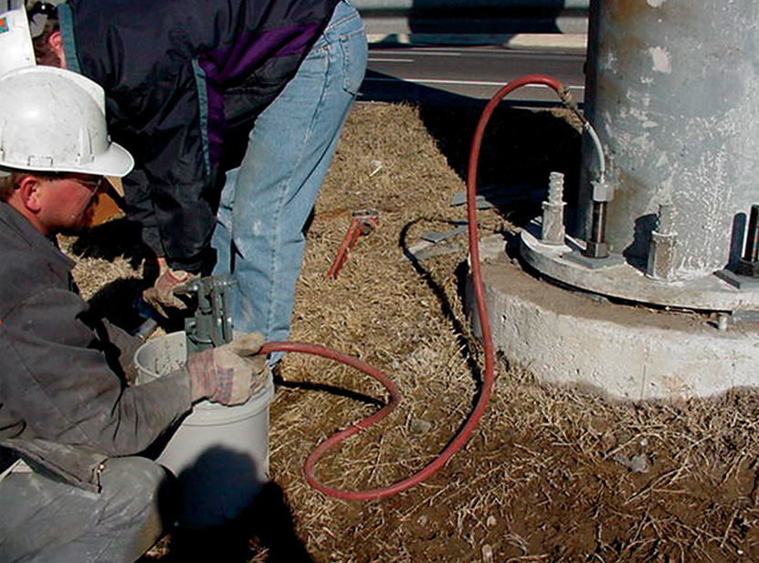
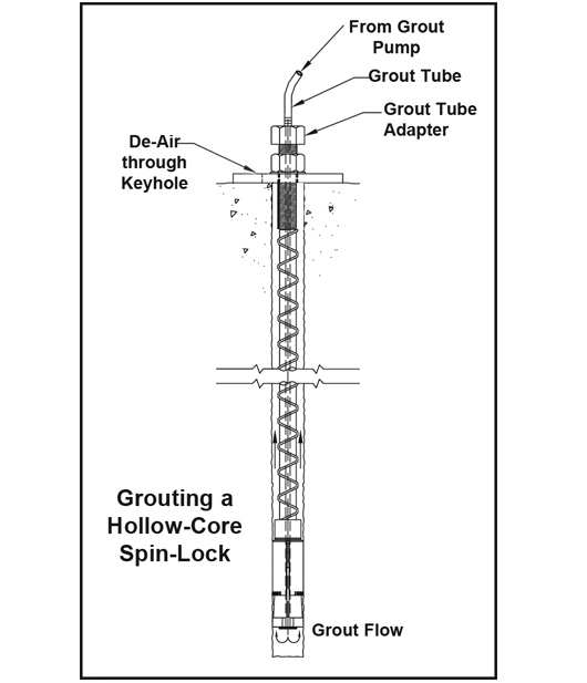
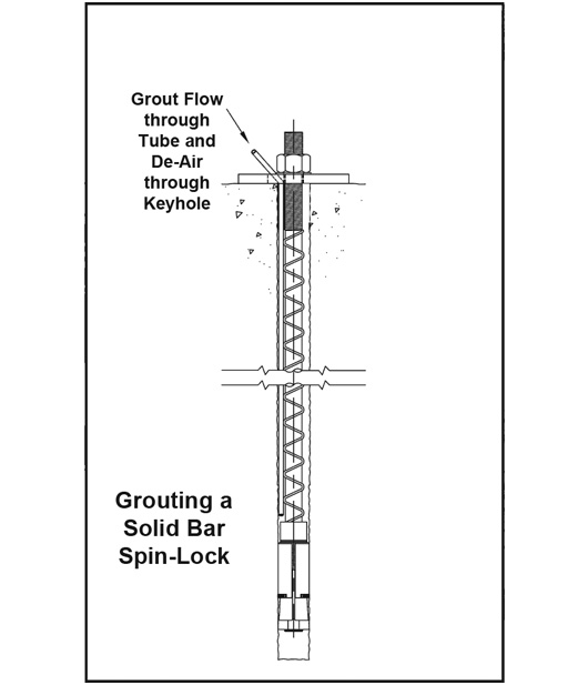
Step 5: Grouting the Anchor
When Grouting the anchor, always grout from the lowest gravitational point. Continue grouting until a steady stream of pure grout is seen coming out around the bearing plate or grout tube, and/or from the de-air tube. For solid anchors, a separate grout tube must be placed in the drill hole (through an opening in the bearing plate) as deep as possible before grouting. Down-grouting of Hollow Core Spin-Locks can be simply grouted through the hollow core by attaching a grout tube adapter to the outer end of the tensioned anchor and grouting. When the grouting is complete, all air and standing water has been removed from the drill hole by displacement.
Williams offers a field installation advising service to aid contractors in the initial installation process of installing all types of concrete anchors. A Williams “Spin-Lock Anchor Installation Video” is available on our YouTube Channel. Contact your Williams sales representative for details.