Micropile Accessories
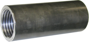
Compression Sleeves
Compression Sleeves are smaller in diameter than standard coupings and are offered for use in splicing steel reinforcement for compression-only micropile designs. Compression Sleeves offer the advantage of designing around smaller diameter casings. Compression Sleeves will not develop the full tensile strength of the bar.

Reducer Coupling
Reducer Couplings are available to transition from a larger diameter bar to a smaller diameter bar. Reducer Couplings will develop the full ultimate strength of the smaller diameter bar.
Micropile Remedial Repair Underpinning Brackets
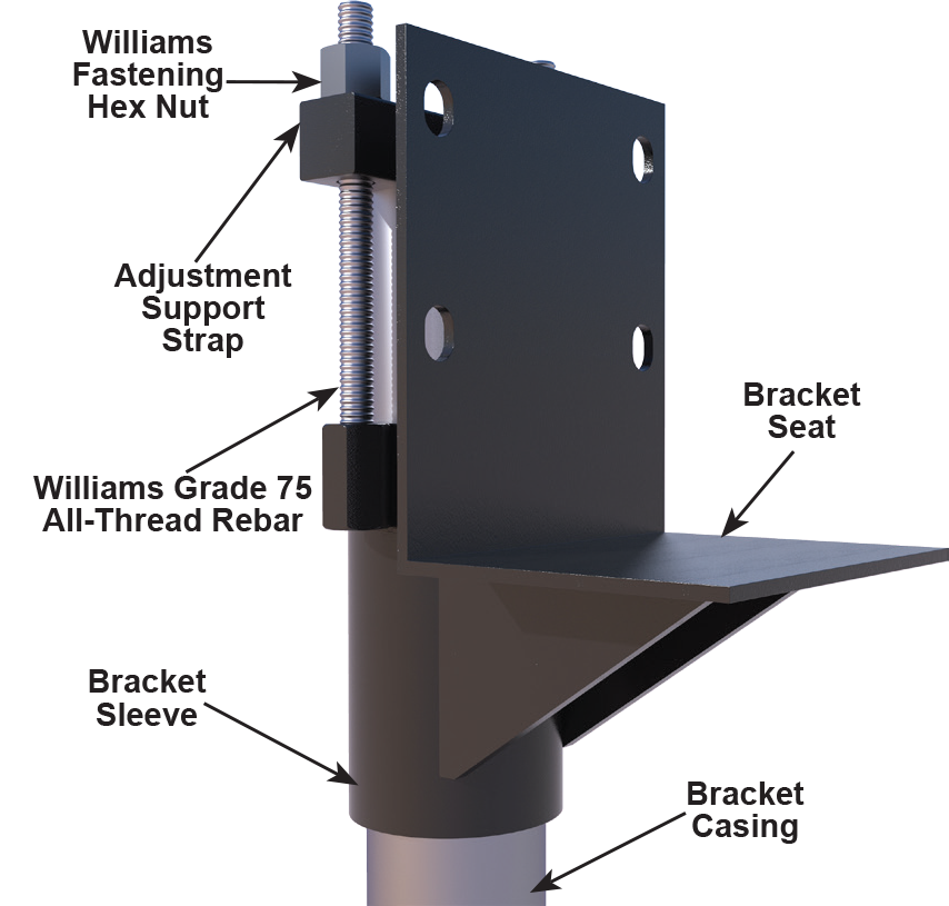
Williams Form Engineering Corp. offers underpinning brackets for tension and/or compression foundation remediation applications. Prior to micropile drilling, the bracket is attached to the footing using concrete anchor bolts. The bracket provides a drill template to ensure pile eccentricity is within the allowable limit. Brackets are offered in three sizes ranging from 20 kip to 63 kip allowable capacities where the bracket is attached to a grouted micropile casing in medium stiff soils (N>4). The unbraced length of micropile is minimum 5’; so per section 1810.2.1 of IBC, a casing length of min 6’ is required to resist buckling and bending stresses. Brackets can be used in soft soils (N<4), however, the capacity may be reduced as the unbraced length of the micropile would be greatly increased in weaker soils. Please consult with a professional engineer to determine allowable working design load.
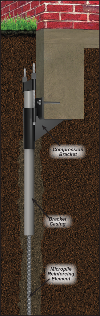
Compression Underpinning Bracket (C)
Supports and raises existing foundations via connection to grouted micropile casing.
| Bracket Number |
Allowable Bracket Capacity * |
Bracket Sleeve | Bracket Seat | Bracket Casing ** | ||||
|---|---|---|---|---|---|---|---|---|
| OD | Wall Thickness |
Bearing Area |
OD | Wall Thickness |
Standard Length |
Yield Stress |
||
| WMS-MPB-20-C | 20 kips (88.9 kN) |
3-1/2” (89 mm) |
1/4” (6.4 mm) |
90 in² (580 cm²) |
2-7/8” (73 mm) |
0.22” (5.5 mm) |
6’ (1.8 m) |
65 KSI (448 Mpa) |
| WMS-MPB-40-C | 40 kips (178 kN) |
5-9/16” (141 mm) |
3/8” (9.5 mm) |
90 in² (580 cm²) |
4-1/2” (114 mm) |
0.44” (11.1 mm) |
6’ (1.8 m) |
65 KSI (448 Mpa) |
| WMS-MPB-63-C | 63 kips (280 kN) |
6-5/8” (168 mm) |
0.43” (11 mm) |
90 in² (580 cm²) |
5-9/16” (141 mm) |
0.26” (6.6 mm) |
6’ (1.8 m) |
36 KSI (248 Mpa) |
* Allowable bracket capacity is based on the usage of an equal or greater size, grade, and length of bracket casing shown in the chart above and assumes the back of the bracket seat is no more than 1.5” from the edge of the footing.
** WFEC does not provide the bracket casing
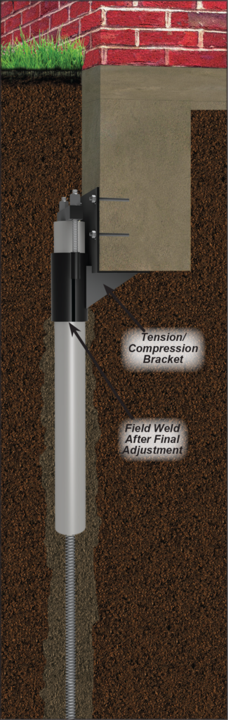
Tension/Compression Underpinning Bracket (TC)
- Supports and raises existing foundations via connection to grouted micropile casing.
- In tension, bracket requires a postive connection to the foundation through four 1” diameter concrete anchors bolts designed to have adequate shear capacity from seismic and wind loads. To complete the tension load path, the bracket must be positively connected to the micopile casing by field welding the bracket sleeve to the mircropile casing or by attaching shear bolts from the bracket sleeve through the micropile casing.
| Bracket Number |
Allowable Bracket Capacity * |
Bracket Sleeve | Bracket Seat | Bracket Casing ** | ||||
|---|---|---|---|---|---|---|---|---|
| OD | Wall Thickness |
Bearing Area |
OD | Wall Thickness |
Standard Length |
Yield Stress |
||
| WMS-MPB-20-TC | 20 kips (89 kN) |
3-1/2” (89 mm) |
1/4” (6.4 mm) |
90 in² (580 cm²) |
2-7/8” (73 mm) |
0.22” (5.5 mm) |
6’ (1.8 m) |
65 KSI (448 Mpa) |
| WMS-MPB-40-TC | 40 kips (178 kN) |
5-9/16” (141 mm) |
3/8” (9.5 mm) |
90 in² (580 cm²) |
4-1/2” (114 mm) |
0.44” (11 mm) |
6’ (1.8 m) |
65 KSI (448 Mpa) |
| WMS-MPB-63-TC | 63 kips (280 kN) |
6-5/8” (168 mm) |
0.43” (11 mm) |
90 in² (580 cm²) |
5-9/16” (141 mm) |
0.26” (6.6 mm) |
6’ (1.8 m) |
36 KSI (248 Mpa) |
* Allowable bracket capacity is based on the usage of an equal or greater size, grade, and length of bracket casing shown in the chart above and assumes the back of the bracket seat is no more than 1.5” from the edge of the footing.
** WFEC does not provide the bracket casing
