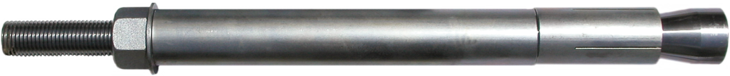
Stainless S-9 Undercut Concrete Anchors
Presented below are four different stainless steel options for the S-9 Undercut Concrete Anchor. Generally, the Stainless 304 B8 Class 1 and the Stainless 316 B8M Class I S-9 Undercut Concrete Anchors are the least expensive and most readily available of the Stainless Steels. The Stainless 304 B8 Class II S-9 boasts the highest strength among the Stainless Steels, while the 316 B8M Class II S-9 provides the combination of high strength and the highest level of corrosion resistance.
Stainless S-9 Undercut Concrete Anchor
ASTM A193 304 B8 & 316 B8M Class I
Structural Properties
| Yield Stress |
Ultimate Stress |
Elongation in 4 Bar Dia |
Reduction of Area |
|---|---|---|---|
| 30 KSI (207 MPa) |
75 KSI (517 MPa) |
30% min | 50% min |
Stainless S-9 Undercut Concrete Anchor – ASTM A193 304 B8 & 316 B8M Class I
| Diameter & Threads per Inch |
Yield Strength (fy) |
Ultimate Strength (fu) |
Drill Hole Diameter (1) |
Minimum Embedment (3000 PSI – f’c) (2) |
Minimum Embedment (6500 PSI – f’c) (2) |
Part Number |
|---|---|---|---|---|---|---|
| 3/8” – 16 (9.5 mm) |
2.32 kips (10.3 kN) |
5.81 kips (25.8 kN) |
7/8” (22 mm) |
4” (102 mm) |
3” (77 mm) |
S9T-03-S4 S9T-03-S6 |
| 1/2” – 13 (13 mm) |
4.26 kips (18.9 kN) |
10.6 kips (47.3 kN) |
7/8” (22 mm) |
5” (127 mm) |
4” (102 mm) |
S9T-04-S4 S9T-04-S6 |
| 5/8” – 11 (16 mm) |
6.78 kips (30.2 kN) |
16.9 kips (75.2 kN) |
1-1/8” (29 mm) |
7” (178 mm) |
6” (153 mm) |
S9T-05-S4 S9T-05-S6 |
| 3/4” – 10 (19 mm) |
10.0 kips (44.6 kN) |
25.1 kips (111 kN) |
1-1/8” (29 mm) |
9” (229 mm) |
7” (178 mm) |
S9T-06-S4 S9T-06-S6 |
| 1” – 8 (25 mm) |
18.2 kips (80.9 kN) |
45.5 kips (202 kN) |
1-5/8” (41 mm) |
14” (356 mm) |
11” (280 mm) |
S9T-08-S4 S9T-08-S6 |
| 1-1/4” – 7 (32 mm) |
29.1 kips (129 kN) |
72.7 kips (323 kN) |
2” (51 mm) |
18” (458 mm) |
14” (356 mm) |
S9T-10-S4 S9T-10-S6 |
| 1-1/2” – 6 (38 mm) |
42.2 kips (188 kN) |
105 kips (469 kN) |
2-1/2” (64 mm) |
23” (585 mm) |
18” (458 mm) |
S9T-12-S4 S9T-12-S6 |
(1) Care should be taken to drill a straight and properly sized hole.
(2) Full ultimate strength of anchor can be achieved at listed embedment depth, provided there are no edge or spacing effects on the anchor.
Stainless S-9 Undercut Concrete Anchor
ASTM A193 304 B8 Class II
Structural Properties
| Diameter Range |
Yield Stress |
Ultimate Stress |
Elongation in 4 Bar Dia |
Reduction of Area |
|---|---|---|---|---|
| 3/8” to 3/4” 9.5 to 19 mm) |
100 KSI (690 MPa) |
125 KSI (862 MPa) |
12% min | 35% min |
| 1” (25 mm) |
80 KSI (552 MPa) |
115 KSI (793 MPa) |
15% min | 35% min |
| 1-1/4” (32 mm) |
65 KSI (448 MPa) |
105 KSI (724 MPa) |
20% min | 35% min |
| 1-1/2” (38 mm) |
50 KSI (375 MPa) |
100 KSI (670 MPa) |
28% min | 45% min |
Stainless S-9 Undercut Concrete Anchor – ASTM A193 304 B8 Class II
| Diameter & Threads per Inch |
Yield Strength (fy) |
Ultimate Strength (fu) |
Drill Hole Diameter (1) |
Minimum Embedment (3000 PSI – f’c) (2) |
Minimum Embedment (6500 PSI – f’c) (2) |
Part Number |
|---|---|---|---|---|---|---|
| 3/8” – 16 (9.5 mm) |
7.75 kips (34.5 kN) |
9.69 kips (43.1 kN) |
7/8” (22 mm) |
5” (127 mm) |
4” (102 mm) |
S9T-03-S42 |
| 1/2” – 13 (13 mm) |
14.2 kips (63.1 kN) |
17.7 kips (78.9 kN) |
7/8” (22 mm) |
8” (204 mm) |
6” (153 mm) |
S9T-04-S42 |
| 5/8” – 11 (16 mm) |
22.6 kips (101 kN) |
28.2 kips (126 kN) |
1-1/8” (29 mm) |
10” (254 mm) |
8” (204 mm) |
S9T-05-S42 |
| 3/4” – 10 (19 mm) |
33.4 kips (149 kN) |
41.8 kips (186 kN) |
1-1/8” (29 mm) |
13” (331 mm) |
10” (254 mm) |
S9T-06-S42 |
| 1” – 8 (25 mm) |
48.4 kips (215 kN) |
69.7 kips (310 kN) |
1-5/8” (41 mm) |
18” (458 mm) |
14” (356 mm) |
S9T-08-S42 |
| 1-1/4” – 7 (32 mm) |
63.0 kips (280 kN) |
102 kips (453 kN) |
2” (51 mm) |
23” (585 mm) |
18” (458 mm) |
S9T-10-S42 |
| 1-1/2” – 6 (38 mm) |
70.2 kips (312 kN) |
141 kips (625 kN) |
2-1/2” (64 mm) |
28” (712 mm) |
22” (559 mm) |
S9T-12-S42 |
(1) Care should be taken to drill a straight and properly sized hole.
(2) Full ultimate strength of anchor can be achieved at listed embedment depth, provided there are no edge or spacing effects on the anchor.
Stainless S-9 Undercut Concrete Anchor
ASTM A193 316 B8M Class II
Structural Properties
| Diameter Range |
Yield Stress |
Ultimate Stress |
Elongation in 4 Bar Dia |
Reduction of Area |
|---|---|---|---|---|
| 3/8” to 3/4” 9.5 to 19 mm) |
96 KSI (662 MPa) |
110 KSI (759 MPa) |
15% min | 45% min |
| 1” (25 mm) |
80 KSI (552 MPa) |
100 KSI (670 MPa) |
20% min | 45% min |
| 1-1/4” (32 mm) |
65 KSI (448 MPa) |
95 KSI (655 MPa) |
25% min | 45% min |
| 1-1/2” (38 mm) |
50 KSI (375 MPa) |
90 KSI (621 MPa) |
30% min | 45% min |
Stainless S-9 Undercut Concrete Anchor – ASTM A193 316 B8M Class II
| Diameter & Threads per Inch |
Yield Strength (fy) |
Ultimate Strength (fu) |
Drill Hole Diameter (1) |
Minimum Embedment (3000 PSI – f’c) (2) |
Minimum Embedment (6500 PSI – f’c) (2) |
Part Number |
|---|---|---|---|---|---|---|
| 3/8” – 16 (9.5 mm) |
7.44 kips (33.1 kN) |
8.53 kips (37.9 kN) |
7/8” (22 mm) |
5” (127 mm) |
4” (102 mm) |
S9T-03-S62 |
| 1/2” – 13 (13 mm) |
13.6 kips (60.6 kN) |
15.6 kips (69.4 kN) |
7/8” (22 mm) |
7” (178 mm) |
5” (127 mm) |
S9T-04-S62 |
| 5/8” – 11 (16 mm) |
21.7 kips (96.5 kN) |
24.9 kips (110 kN) |
1-1/8” (29 mm) |
9” (229 mm) |
7” (178 mm) |
S9T-05-S62 |
| 3/4” – 10 (19 mm) |
32.1 kips (143 kN) |
36.7 kips (163 kN) |
1-1/8” (29 mm) |
12” (305 mm) |
9” (229 mm) |
S9T-06-S62 |
| 1” – 8 (25 mm) |
48.5 kips (216 kN) |
60.6 kips (269 kN) |
1-5/8” (41 mm) |
16” (407 mm) |
13” (331 mm) |
S9T-08-S62 |
| 1-1/4” – 7 (32 mm) |
63.0 kips (280 kN) |
92.0 kips (409 kN) |
2” (51 mm) |
22” (559 mm) |
17” (432 mm) |
S9T-10-S62 |
| 1-1/2” – 6 (38 mm) |
70.2 kips (312 kN) |
126 kips (562 kN) |
2-1/2” (64 mm) |
26” (660 mm) |
21” (534 mm) |
S9T-12-S62 |
(1) Care should be taken to drill a straight and properly sized hole.
(2) Full ultimate strength of anchor can be achieved at listed embedment depth, provided there are no edge or spacing effects on the anchor.
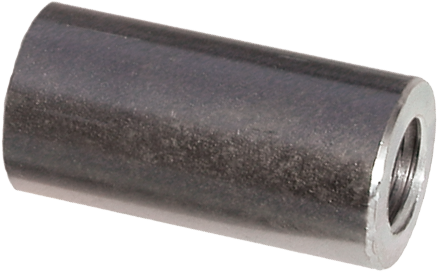
C2T Stop-Type Couplings & C2D Flange Couplings
| Bar Diameter |
Outside Diameter |
Overall Length |
Stop-Type Part Number |
Flange Coupling | |
|---|---|---|---|---|---|
| Flange Size | Part Number | ||||
| 3/8” (9.5 mm) |
3/4” (19 mm) |
1-1/2” (38 mm) |
C2T-03 | 2” x 2” (51 x 51 mm) |
C2D-03 |
| 1/2” (13 mm) |
3/4” (19 mm) |
1-1/2” (38 mm) |
C2T-04 | 2” x 2” (51 x 51 mm) |
C2D-04 |
| 5/8” (16 mm) |
1” (25 mm) |
1-3/4” (45 mm) |
C2T-05 | 2” x 2” (51 x 51 mm) |
C2D-05 |
| 3/4” (19 mm) |
1-1/8” (29 mm) |
2” (51 mm) |
C2T-06 | 2” x 2” (51 x 51 mm) |
C2D-06 |
| 1” (25 mm) |
1-1/2” (38 mm) |
3” (76 mm) |
C2T-08 | 3” x 3” (76 x 76 mm) |
C2D-08 |
| 1-1/4” (32 mm) |
1-7/8” (48 mm) |
3-3/4” (95 mm) |
C2T-10 | 3” x 3” (76 x 76 mm) |
C2D-10 |
| 1-1/2” (38 mm) |
2-1/4” (57 mm) |
5” (127 mm) |
C2T-12 | 3” x 3” (76 x 76 mm) |
C2D-12 |
H1F Heavy Duty Hex Nuts

| Bar Diameter |
Across Flats |
Across Corners |
Thickness | Part Number |
|---|---|---|---|---|
| 3/8” (9.5 mm) |
11/16” (18 mm) |
0.8” (20 mm) |
23/64” (9 mm) |
H1F-03 |
| 1/2” (13 mm) |
7/8” (22 mm) |
1.0” (26 mm) |
31/64” (12 mm) |
H1F-04 |
| 5/8” (16 mm) |
1-1/16” (27 mm) |
1.2” (31 mm) |
39/64” (16 mm) |
H1F-05 |
| 3/4” (19 mm) |
1-1/4” (32 mm) |
1.4” (37 mm) |
47/64” (19 mm) |
H1F-06 |
| 1” (25 mm) |
1-5/8” (41 mm) |
1.9” (48 mm) |
63/64” (25 mm) |
H1F-08 |
| 1-1/4” (32 mm) |
2” (51 mm) |
2.3” (59 mm) |
1-7/32” (31 mm) |
H1F-10 |
| 1-1/2” (38 mm) |
2-3/8” (60 mm) |
2.7” (70 mm) |
1-15/32” (37 mm) |
H1F-12 |
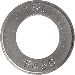
R9F Hardened Washers
| Bar Diameter |
Outside Diameter |
Inside Diameter |
Thickness | Part Number |
|---|---|---|---|---|
| 3/8” (9.5 mm) |
1” (25 mm) |
7/16” (11 mm) |
5/64” (2 mm) |
R9F-03-436 |
| 1/2” (13 mm) |
1-1/16” (27 mm) |
17/32” (14 mm) |
9/64” (3.56 mm) |
R9F-04-436 |
| 5/8” (16 mm) |
1-5/16” (33 mm) |
11/16” (17 mm) |
9/64” (3.6 mm) |
R9F-05-436 |
| 3/4” (19 mm) |
1-7/16” (37 mm) |
13/16” (21 mm) |
9/64” (3.6 mm) |
R9F-06-436 |
| 1” (25 mm) |
2” (51 mm) |
1-1/8” (29 mm) |
5/32” (4 mm) |
R9F-08-436 |
| 1-1/4” (32 mm) |
2-1/2” (64 mm) |
1-3/8” (35 mm) |
5/32” (4 mm) |
R9F-10-436 |
| 1-1/2” (38 mm) |
3” (76 mm) |
1-5/8” (41 mm) |
5/32” (4 mm) |
R9F-12-436 |
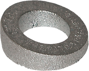
R8M Beveled Washers
| Bar Diameter |
Degree of Bevel |
Outside Diameter |
Inside Diameter |
Maximum Thickness |
Minimum Thickness |
Part Number |
|---|---|---|---|---|---|---|
| 3/8” (9.5 mm) |
14° | 1-1/4” (32 mm) |
9/16” (14 mm) |
7/16” (11 mm) |
1/8” (3 mm) |
R8M-03 |
| 1/2” (13 mm) |
14° | 1-1/4” (32 mm) |
9/16” (14 mm) |
7/16” (11 mm) |
1/8” (3 mm) |
R8M-04 |
| 5/8” (16 mm) |
11° | 1-9/16” (40 mm) |
13/16” (21 mm) |
1/2” (13 mm) |
3/16” (5 mm) |
R8M-06 |
| 3/4” (19 mm) |
11° | 1-9/16” (40 mm) |
13/16” (21 mm) |
1/2” (13 mm) |
3/16” (5 mm) |
R8M-06 |
| 1” (25 mm) |
15° | 2-1/16” (52 mm) |
1” (25 mm) |
3/4” (19 mm) |
1/4” (6 mm) |
R8M-08S |
| 1-1/4” (32 mm) |
15° | 3-3/8” (86 mm) |
1-9/16” (40mm) |
1-15/64” (31 mm) |
3/8” (9.5 mm) |
R8M-12S |
| 1-1/2” (38 mm) |
15° | 3-1/2” (89 mm) |
1-3/4” (45 mm) |
1-1/4” (32mm) |
3/8” (9.5 mm) |
R8M-13S |
To achieve full strength of the nut, beveled washers must be used in conjunction with a hardened washer.
