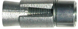
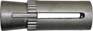
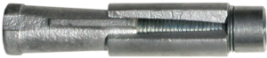
R7S 150 KSI Spin-Lock Concrete Anchor
The R7S Spin-Lock incorporates a high strength post-tension steel giving the designer the highest strength to anchor diameter ratio available for use with the Spin-Lock head assembly

R7S Structural Properties
| Yield Stress |
Ultimate Stress |
Elongation in 20 Bar Dia. |
Reduction of Area |
|---|---|---|---|
| 120 KSI (827 MPa) |
150 KSI (1034 MPa) |
4% min | 20% min |
R7S 150 KSI Spin-Lock Concrete Anchor
ASTM A722
| Diameter & Threads per Inch |
Yield Strength (fy) |
Ultimate Strength (fu) |
Drill Hole Diameter (1) |
Type Head Assembly |
Torque (ft-lbs) | Minimum Embedment (3000 PSI – f’c) (5) |
Minimum Embedment (6500 PSI – f’c) (5) |
Part Number |
|
|---|---|---|---|---|---|---|---|---|---|
| To Expand Shell (2) |
On Nut for Tension (3) |
||||||||
| 1” – 8 (25 mm) |
72.7 kips (324 kN) |
90.9 kips (404 kN) |
1-3/4” (44 mm) |
C 14 | 500 ft-lbs (650*) |
680 ft-lbs | 17” (432 mm) |
13” (330 mm) |
R7S08C14 |
| 1-1/4” – 7 (32 mm) |
116 kips (517 kN) |
145 kips (646 kN) |
2-1/2” (64 mm) |
B 20 | 750 ft-lbs (1200*) |
Note (4) | 23” (584 mm) |
18” (457 mm) |
R7S10B20 |
| 1-1/2” – 6 (38 mm) |
169 kips (750 kN) |
210 kips (937 kN) |
3” (76 mm) |
B 24 | 1000 ft-lbs (1700*) |
Note (4) | 30” (762 mm) |
23” (584 mm) |
R7S12B24 |
| 1-7/8” – 8 (48 mm) |
289 kips (1286 kN) |
362 kips (1609 kN) |
3-1/2” (89 mm) |
C 28 | 1000 ft-lbs (2000*) |
Note (4) | 43” (1092 mm) |
33” (838 mm) |
R7S15C28 |
(*) Do not exceed these numbers
(1) Care should be taken to drill a straight and properly sized hole.
(2) More torque may be required on long anchors or if the head assembly is next to rebar. Consult your Williams Representative for more specific details.
(3) Torque value listed will achieve approximate load of 50% of the anchor ultimate strength, and is based on the torque tension curves here.
(4) Stress to desired tensile load using a hollow ram hydraulic jack. Consult your Williams Representative.
(5) Full ultimate strength of anchor can be achieved at listed embedment depth, provided there are no edge or spacing effects on the anchor.
– Spin-Locks come standard with 12” of threaded area. Other lengths available upon request.
– WILLIAMS reserves the right to ship full length or coupled units as necessary.
Head Assemblies
The Williams Spin-Lock anchor assembly gives full 300° bearing area. The smooth shell design allows for maximum shell to concrete contact and eliminates “point of contact” created by serrated designs. The cone design supports the shell 300°, thereby eliminating any possible collapse of the shell under high load conditions. The thrust ring stop in front of the shell prevents any possible rebound of the expanded shell down the cone when subjected to nearby blasting. The Williams Spin-Lock anchor has been field proven on the world’s largest projects to far exceed in tension capacity any other mechanical anchor on the market.
| Head Assembly |
Drill Hole Diameter |
Diameter & Threads per Inch |
Cone | Shell | Thrust Ring | Slip Rings |
Overall Assembly Length |
|||
|---|---|---|---|---|---|---|---|---|---|---|
| Length | Part No. | Length | Part No. | Diameter | Thickness | |||||
| B20 | 2-1/2” (65 mm) |
1-1/4” – 7 NC (32 mm) |
4” (102 mm) |
LC-250 | 4” (102 mm) |
LS-250 | 2-1/8” (54 mm) |
1-1/4” (32 mm) |
9/64” (3.6 mm) |
9-1/2” (241 mm) |
| B24 | 3” (76 mm) |
1-1/2” – 6 NC (38 mm) |
5-1/2” (140 mm) |
LC-300 | 5-1/2” (140 mm) |
LS-300 | 2-3/4” (70 mm) |
1-1/2” (38 mm) |
1/2” (12.7 mm) |
12-7/8” (325 mm) |
| C14 | 1-3/4” (44 mm) |
1” – 8 NC (25 mm) |
4-1/4” (108 mm) |
LCF-175-8 | 3-3/4” (95 mm) |
LS-175 | 1-5/8” (41 mm) |
1-1/2” (38 mm) |
1/16” (1.6 mm) |
9-5/8” (244 mm) |
| C28 | 3-1/2” (89 mm) |
1-7/8” – 8 UN (48 mm) |
7” (178 mm) |
LCF-350-16 | 6” (152 mm) |
LS-350 | 2-7/8” (73 mm) |
1-7/8” (48 mm) |
1/8” (3.2 mm) |
15-1/8” (384 mm) |
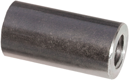
Coupled Head Assemblies
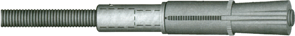
Williams can manufacture Spin-Lock Anchor systems with the use of a transition coupling, which allows the anchor to be designed with a continuously workable thread-form. This is advantageous when the anchor length may need to be adjusted in the field due to variable site conditions. The transition coupling engages a continuously threaded U.N. bar into the head assembly and the All-Thread Bar (typically Grade 75 & Grade 80 All-Thread Rebar or 150 KSI All-Thread-Bar) is attached to the other end of the coupling.
C2T Stop-Type Couplings
| Bar Diameter |
Outside Diameter |
Overall Length |
Part Number |
|---|---|---|---|
| 1” (25 mm) |
1-1/2” (38 mm) |
3” (76 mm) |
C2TN-08 |
| 1-1/4” (32 mm) |
1-7/8” (48 mm) |
3-3/4” (95 mm) |
C2TN-10 |
| 1-1/2” (38 mm) |
2-1/4” (57 mm) |
5” (127 mm) |
C2TN-12 |
| 1-7/8” (48 mm) |
2-7/8” (73 mm) |
6” (152 mm) |
C2TU-15 |
H1F Heavy Duty Hex Nuts

| Bar Diameter |
Across Flats |
Across Corners |
Thickness | Part Number |
|---|---|---|---|---|
| 1” (25 mm) |
1-5/8” (41 mm) |
1.9” (48 mm) |
63/64” (25 mm) |
H1FN-08 |
| 1-1/4” (32 mm) |
2” (51 mm) |
2.3” (59 mm) |
1-7/32” (31 mm) |
H1FN-10 |
| 1-1/2” (38 mm) |
2-3/8” (60 mm) |
2.7” (70 mm) |
1-15/32” (37 mm) |
H1FN-12 |
| 1-7/8” (48 mm) |
2-15/16” (75 mm) |
3.4” (86 mm) |
1-27/32” (47 mm) |
H1FU-15 |
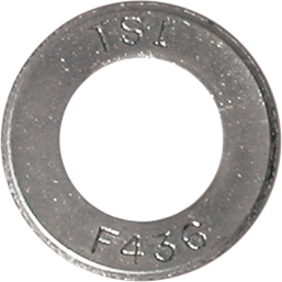
R9F Hardened Washers
| Bar Diameter |
Outside Diameter |
Inside Diameter |
Thickness | Part Number |
|---|---|---|---|---|
| 1” (25 mm) |
2” (51 mm) |
1-1/16” (29 mm) |
5/32” (4 mm) |
R9F-08-436 |
| 1-1/4” (32 mm) |
2-1/2” (64 mm) |
1-3/8” (35 mm) |
5/32” (4 mm) |
R9F-10-436 |
| 1-1/2” (38 mm) |
3” (76 mm) |
1-5/8” (41 mm) |
5/32” (4 mm) |
R9F-12-436 |
| 1-7/8” (48 mm) |
3-3/4” (95 mm) |
2-1/8” (54 mm) |
7/32” (5.6 mm) |
R9F-16-436 |
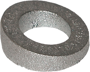
R8M Beveled Washers
| Bar Diameter |
Degree of Bevel |
Outside Diameter |
Inside Diameter |
Maximum Thickness |
Minimum Thickness |
Part Number |
|---|---|---|---|---|---|---|
| 1” (25 mm) |
15° | 2-1/16” (52 mm) |
1” (25 mm) |
3/4” (19 mm) |
1/4” (6 mm) |
R8M-08-15 |
| 1-1/4” (32 mm) |
15° | 3-3/8” (86 mm) |
1-9/16” (40mm) |
1-1/4” (32 mm) |
3/8” (9.5 mm) |
R8M-12-15 |
| 1-1/2” (38 mm) |
15° | 3-1/2” (89 mm) |
1-3/4” (45 mm) |
1-1/4” (32mm) |
3/8” (9.5 mm) |
R8M-13-15 |
| 1-7/8” (48 mm) |
5° | 3-9/16” (91 mm) |
2-1/16” (52 mm) |
13/16” (21 mm) |
1/2” (13 mm) |
R8M-16-5 |
To achieve full strength of the nut, beveled washers must be used in conjunction with a hardened washer.
